Wind Loads Direction Parallel To Ridge Line Or Flat Roof

Asce702w By Alex Tomanovich Asce702w Is A Spreadsheet Program Written In Ms Excel For The Purpose Of W Structural Engineering Concrete Mix Design Spreadsheet

5 Glorious Hacks Glass Roofing Dreams Porch Roofing Curb Appeal Roofing Light Interiors Patio Roofing Corrugated Fibreglass Roof Metal Roof Roof Construction

Framing A Roof With Change Of Pitch Google Search Roof Framing Patio Roof Front Porch Design

Weathervane Cupola Copper Finial Assembly And Installation Instructions Cupolas Garage Cupola Barn Cupola

Figure2 55 Jpg 424 389 Ventilation Design Ventilation Roof Design
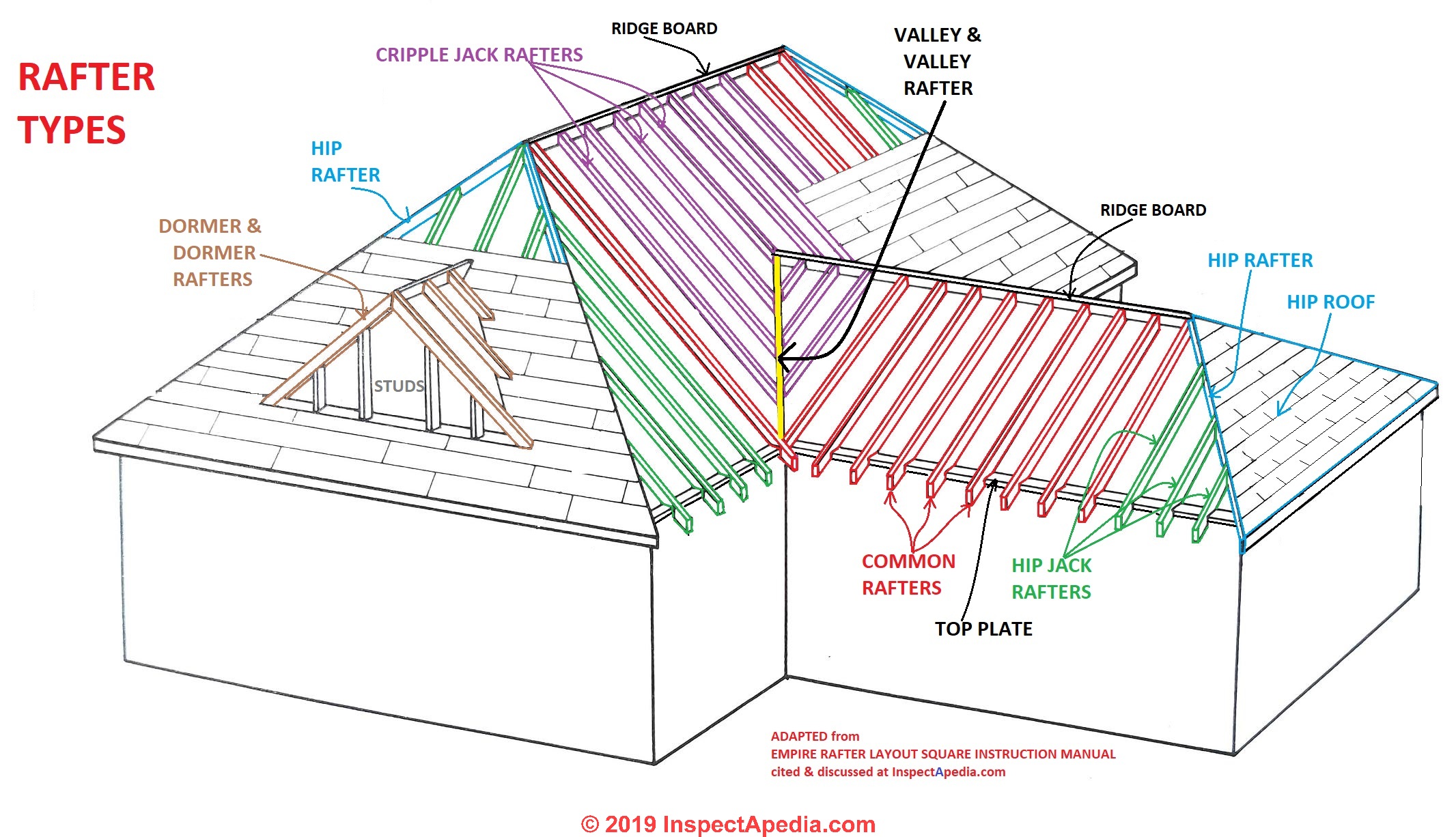
Roof Framing Definition Of Types Of Rafters Definition Of Collar Ties Rafter Ties Structural Ridge Beams Causes Of Roof Collapse Wall Spread

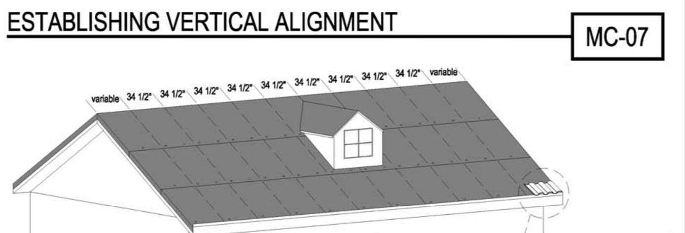
Set the type of the cover according to ec.
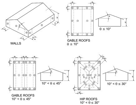
Wind loads direction parallel to ridge line or flat roof.

Wind Load Calculations Free Wind Load Calculator
Ce Center Designing For High Winds

Way To Structure Gable Roof With Cathedral Ceiling Cathedral Ceiling Building A House Roof Framing
Ftp Ftp Co Dekalb In Us Auburn Outgoing Bpd Routingprojectsforentitiesoutsideofcitynetwork 2018 Bldg Newstruc 2018 00000051 Culvers 121touringdr 2018 052 20auburn 20structural 20calcs 20sealed Pdf

Avalanche Assessment Sawchuk 5 Jpg 328 482
Installation Guides Eagle Roofing

The Seven Deadly Sins Of Trussed Rafter Construction Part 1 Local Architects Direct

Collar Ties Rafter Ties Purlins And Braces Jwk Inspections Roof Framing Framing Construction Roof Trusses

Chapter 35 Building Construction Real Estate U

Pin By Knox White On Church Look Rafter Ridge Board Building Roof

Pdf Wind Loads On Gable Type Canopy Roof
Https Www Iccsafe Org Wp Content Uploads 2018 Irc Accessory Structursdecks Carports And Patio Covers Min Pdf
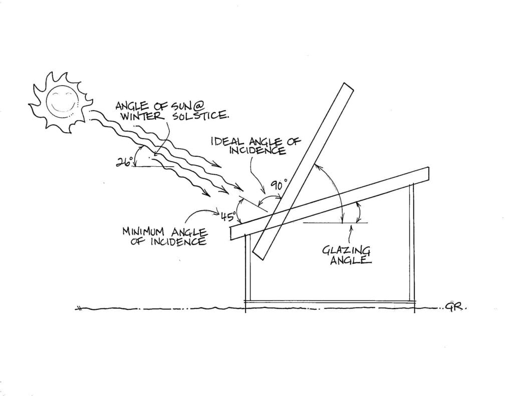
Choosing The Right Angle For Your Greenhouse Roof Ceres Greenhouse

How To Diy Shed Roof Framing Step By Step Guide

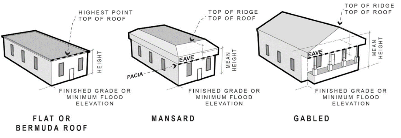
Top 20 Roof Types And Pros Cons Roof Styles Design Architecture

Major Horizontal Support Of Floor System Girder

Cross Ventilation In House Designs For Natural Passive Air Flow House Ventilation Ventilation Design Passive Design

How To Build A Berm Urbanlandscape Landscape Design Burm Landscaping Landscape
Https Encrypted Tbn0 Gstatic Com Images Q Tbn 3aand9gctd Knwg9 Aqvxobeiwrmo Ycxevyvqv5dpu08wjq Qygicqy3m Usqp Cau
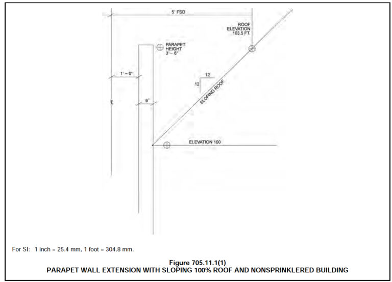
When Does The Code Require Parapets What Construction And Fire Resistance Requirements Exist For Parapets Woodworks
Https Fortifiedhome Org Wp Content Uploads 2019 05 Fortified Home High Wind Standards 2015 Pdf
Bioclimatica Full
Chapter 118 Land Use Regulations Code Of Ordinances Fort Myers Fl Municode Library
Https Cdn2 Hubspot Net Hubfs 1608284 Documents Install Guides 34 20corrugated 20install 20guide Pdf
Source : pinterest.com
