Wind Force On Roof In Longitudinal Direction

Pin On Civil Engineering

Asce702w By Alex Tomanovich Asce702w Is A Spreadsheet Program Written In Ms Excel For The Purpose Of W Structural Engineering Concrete Mix Design Spreadsheet
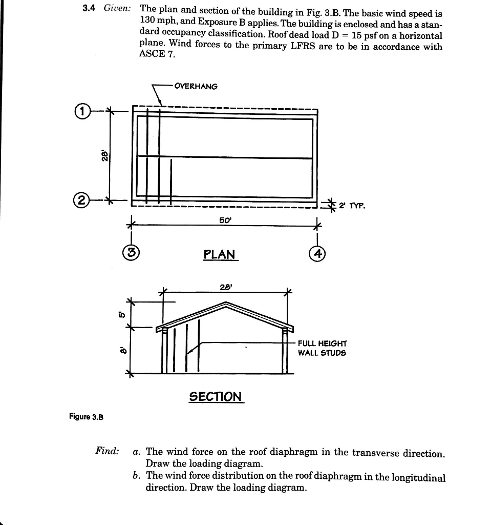
Solved 3 4 Given The Plan And Section Of The Building In Chegg Com
Wind Load Calculator

Find The Wind Load In The Longitudinal Direction O Chegg Com
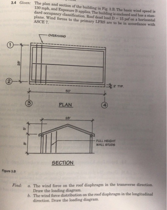
Solved 3 4 Given The Plan And Section Of The Building In Chegg Com

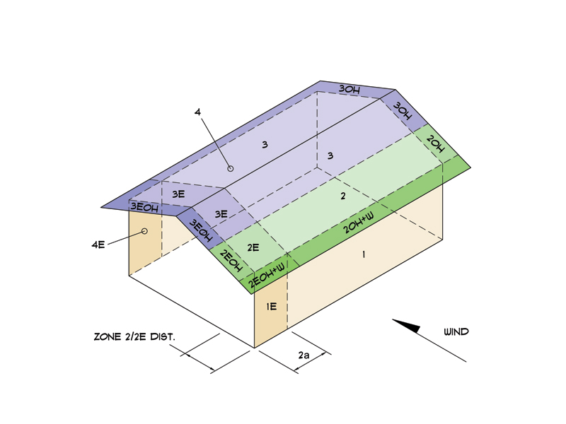
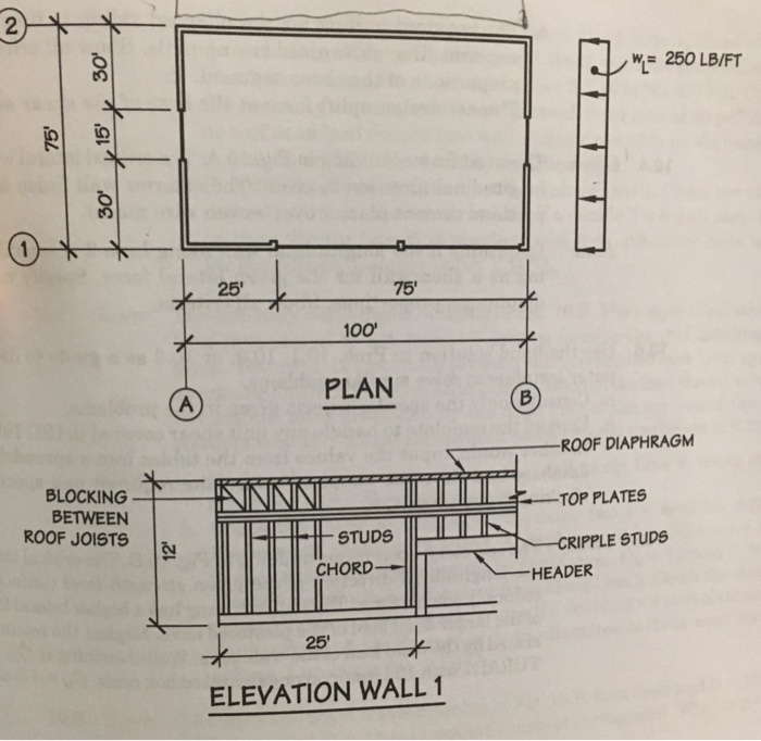
In the longitudinal direction when the force acts on the gable ends of the building the first component to interact with the load is the cladding materials sheeting.
Wind force on roof in longitudinal direction.
Wind Loading Analysis Mwfrs And Components Cladding Engineers Edge
Https Www Mdpi Com 2076 3417 9 12 2466 Pdf

Types Of Loads On Structures Diagram Architecture Timber Frame Construction Footing Foundation
10 1 Given The Single Story Wood Frame Building I Chegg Com

Reinforced Concrete Inverted Upstand Beam Slab Support Details Reinforced Concrete Beams Concrete
Http Site Iugaza Edu Ps Sshihada Files 2012 02 Handout 10 2018 Pdf

Dynamic Monitoring Of A Stadium Suspension Roof Wind And Temperature Influence On Modal Parameters And Structural Response Sciencedirect

Lawriter Oac

Pdf Rooftop Equipment Wind Load And Mitigation Techniques

Some Useful Tips To Study The Drawing Of Plinth Beam In Construction Site Structural Drawing Construction Estimating Software Plinths

Field Monitoring And Wind Tunnel Study Of Wind Effects On Roof Overhang Of A Low Rise Building Wang 2020 Structural Control And Health Monitoring Wiley Online Library
Ftp Ftp Co Dekalb In Us Auburn Outgoing Bpd Routingprojectsforentitiesoutsideofcitynetwork 2018 Bldg Newstruc 2018 00000051 Culvers 121touringdr 2018 052 20auburn 20structural 20calcs 20sealed Pdf

Pdf Wind Load Combinations Including Torsion For Rectangular Medium Rise Buildings

Les Study Of Wind Pressure And Flow Characteristics Of Flat Roof Mounted Solar Arrays Sciencedirect

Field Measurements Of Wind Effects On A Low Rise Building With Roof Overhang During Typhoons Sciencedirect

Response Of Toe Nailed Roof To Wall Connections To Extreme Wind Loads In A Full Scale Timber Framed Hip Roof Sciencedirect
Pdf Wind Loads On Low Rise Building Models With Different Roof Configurations

Roof Structure Guide
Https Encrypted Tbn0 Gstatic Com Images Q Tbn 3aand9gcqwrlc 6s5w9yd2dykvev0l895lwbsap3z6oz6gvgecfxg97kpw Usqp Cau

Doc Wind Load Calculation Asce Vivek Anand Academia Edu
Https Ascelibrary Org Doi Pdf 10 1061 28asce 29ae 1943 5568 0000209
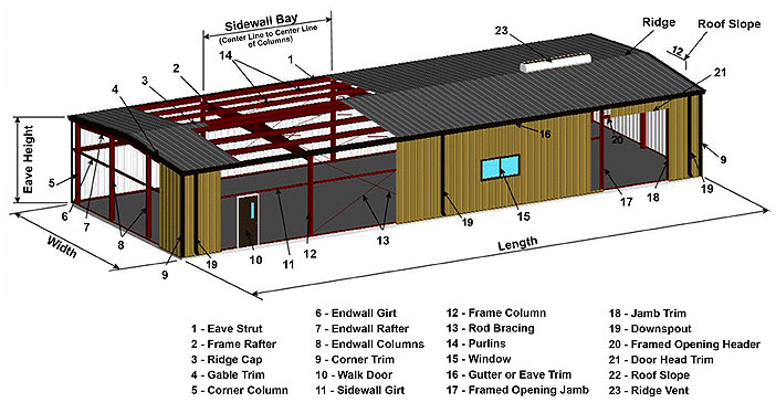
Metal Buildings 101 The Basics Of Metal Building Systems Construction
Https Www Jstor Org Stable 44644045
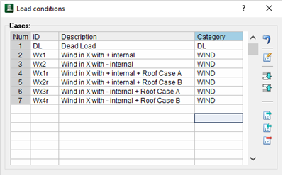
Wind Load Generation On Load Areas Ram Staad Opentower Wiki Ram Staad Opentower Bentley Communities
Source : pinterest.com
